
One of the main questions we often get asked when building a PC is how to wire up cables accurately. This is a complex but vital step of the PC building process that can leave you with a PC that won’t turn on if wired up incorrectly, adding unnecessary troubleshooting that can easily be avoided.
In this guide, we’ll explain how to correctly wire up all of your PC cables. Whether you’re a first-time builder or someone who hasn’t upgraded their system in a while, this article is for you! We’ve covered all of the necessary cables for a PC build, including power supply cabling, case front panel cables, different types of RGB headers, fan and CPU cooler cables, along with troubleshooting steps that can help guide you through quick fixes if your PC build isn’t working properly.
We’ve also put together a video on PC cables and wiring, which follows the same structure as this article and is worth watching alongside as a visual aid for those building a PC right now!
Universal Power Cables
CPU Power
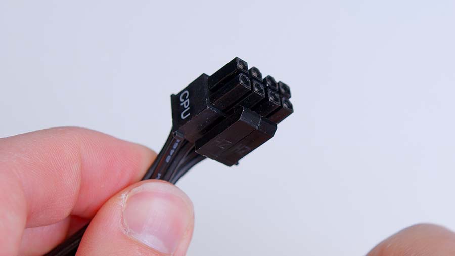
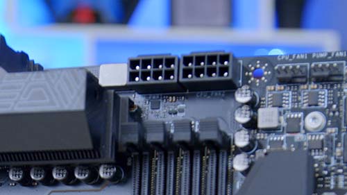
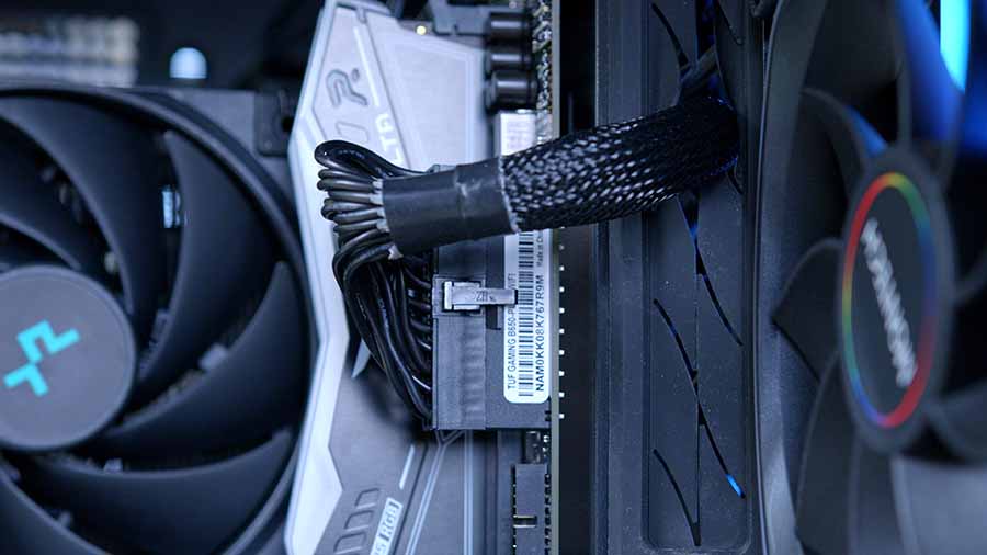
The CPU power cable has a 4+4 form factor. Typically, CPU power headers have eight pins but can be split in half as two four-pin cables. The headers for CPU power are located at the top left of a motherboard, and the number of available headers will change depending on which board you’ve picked up.
As a general rule of thumb, all motherboards supply an eight-pin header as standard to power the CPU. However, other motherboards may provide an additional four-pin or eight-pin header. Motherboards with more power for CPU overclocking will have more CPU headers.
It is worth noting that CPU power cables look incredibly similar to PCI-E cables (used for graphics cards). Double-check that the header says ‘CPU’ or ‘EPS_CPU’ to ensure the correct cable is being plugged in. CPU cables are also keyed, so they can only go in one way. Typically, the CPU power cable clip latches on to a small notch on the motherboard header, which secures it in place. Equally, the clip must be squeezed to remove the CPU power cable.
To showcase the differences in motherboards, the MSI MEG X670E ACE is a top-end option designed to accommodate a CPU like the Ryzen 9 7900X, which has a higher power draw and can be overclocked. For this reason, it comes with two eight-pin power connectors.
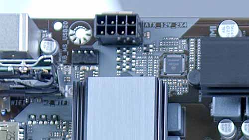
Alternatively, the Gigabyte B760 DS3H AX is an Intel-based motherboard aimed at budget PC builds. Because of this, the B760 DS3H AX only comes with a singular eight-pin CPU header, compared to the MEG X670E ACE, which has two. We recommend plugging in all of the available headers regardless of whether you plan on overclocking.
Motherboard Power
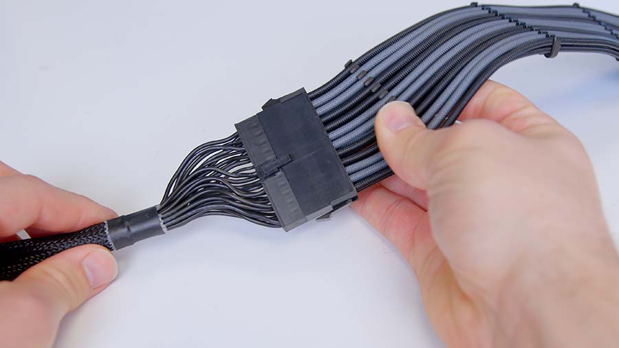
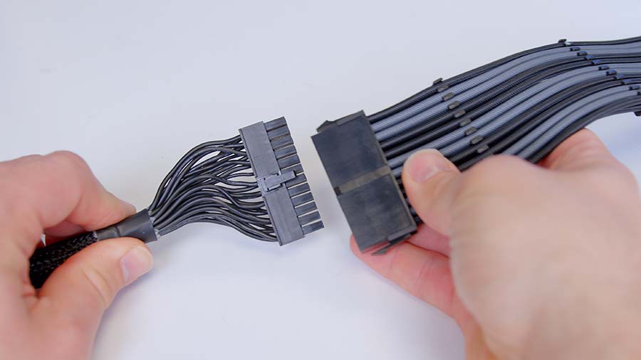
Motherboards require a lot of power compared to other components, as fans, SSDs, RAM, and RGB are all powered by your board. Due to this, the motherboard power cable is the most recognisable, as it is the biggest header with a form factor of 20+4 pins, or 24 pins. Some modern power supplies bundle this header into a single 24-pin cable, while other PSUs can split it out for older motherboards that only use 20 pins.
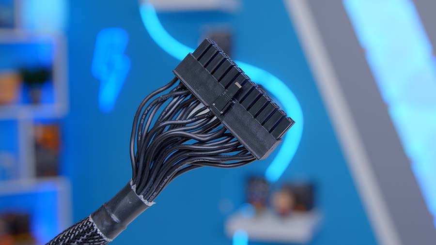
Much like CPU power connectors, motherboard cables are keyed so they can only be inserted into the header one way. Motherboard cables are a bit stiffer than CPU power cables, so a little force might be required to seat the motherboard power correctly. But you’ll know the cable is in once the small plastic clip is engaged.
Graphics Card Power
The final common cable found across most PC builds is graphics card power (or GPU power). Graphics card cables start to complicate things because the standard for powering GPUs has shifted over the past few years.
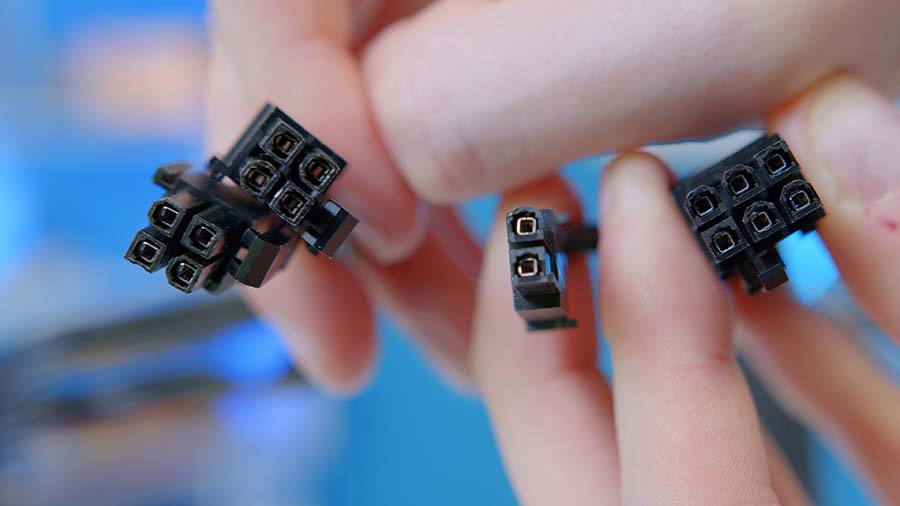
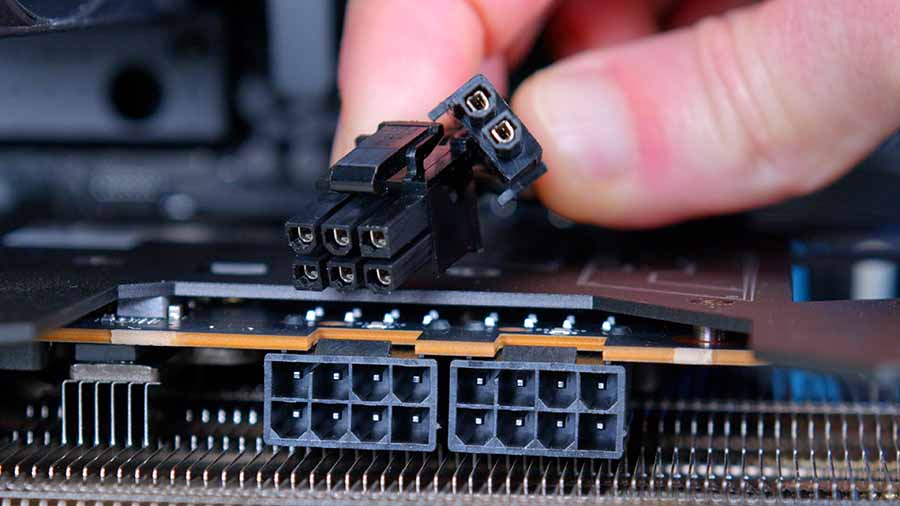
The older and more traditional GPU power cable is a PCI-E 6+2 pin. GPU power utilises a similar eight-pin form factor to CPU power cables, but instead of splitting into a 4+4 configuration, graphics card headers split into 6+2, which makes it a bit easier to distinguish the two despite looking the same.
The number of 6+2 headers you’ll need for a graphics card will greatly depend on the GPU in your PC build. We installed an RX 7900 GRE in our wiring guide video, which uses two eight-pin headers or two 6+2-pin cables. Two eight-pin cables are a relatively common standard across most mid-range graphics cards, but top-end GPUs like the RX 7900 XT and RX 7900 XTX will use three or more to accommodate the higher power draw.
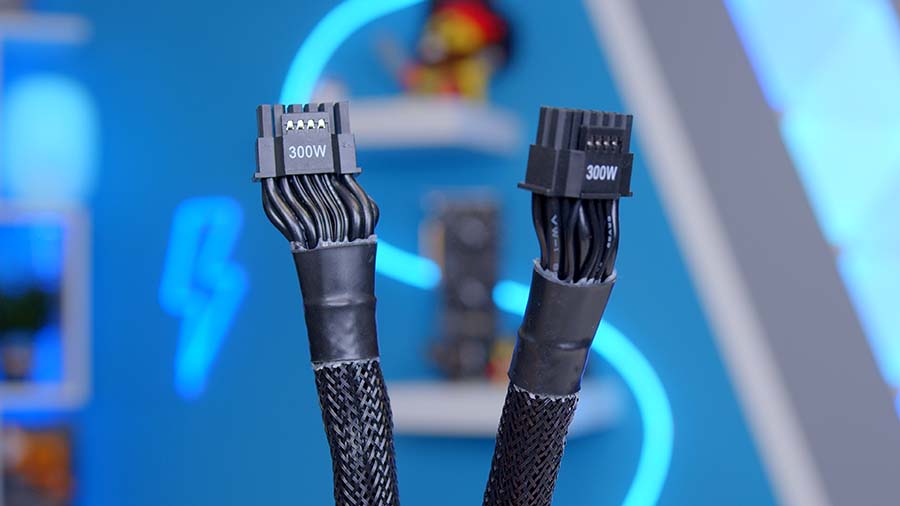
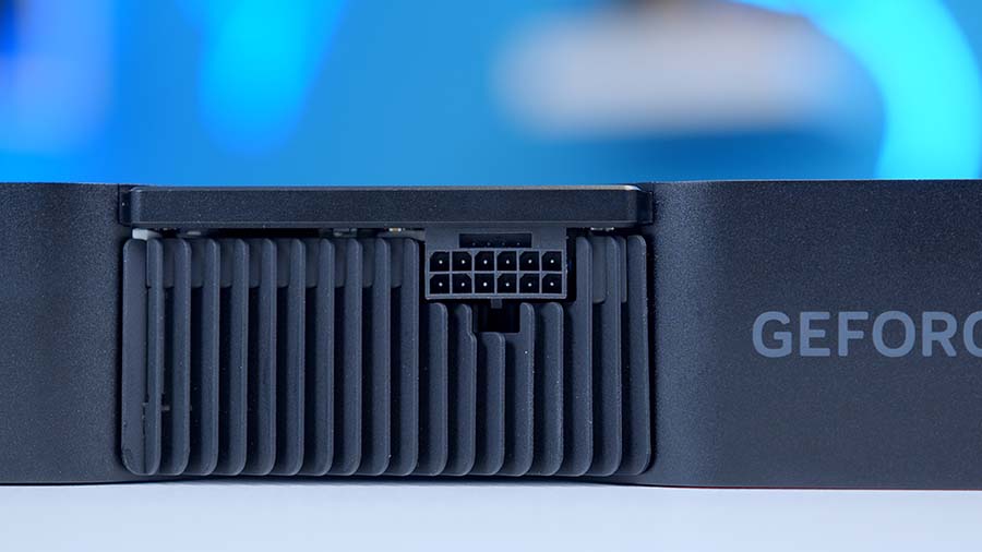
We’ve said graphics card power has become a bit more complicated in the past few years due to the introduction of a standard known as ATX 3.0. Because modern graphics cards naturally consume more power due to a rise in performance, the ATX 3.0 standard was brought into play for manufacturers to pipe up to 600W through a single cable.
There aren’t (at the time of writing) any graphics cards that require this much power, but NVIDIA has moved all of their RTX 4000 range of GPUs over to this design, which means the traditional 6+2 pin header is now a 12VHPWR cable.
This change means that anyone with an RTX 4000 graphics card will need to use an ATX 3.0 compatible power supply with a 12VHPWR cable. Alternatively, a PCI-E adapter that comes with all RTX 4000 GPUs connects 8+2 pin headers to a 12VHPWR cable. The 12VHPWR adapters aren’t the nicest-looking cables, but this is the solution for those unwilling to pick up a new PSU.
We recommend researching which type of header your GPU will need by looking at the manufacturer’s website. Generally, AMD uses the 8+2-pin standard (which will likely change with Radeon 8000 cards), but new NVIDIA cards utilise 12VHPWR.
Additional Power Cables
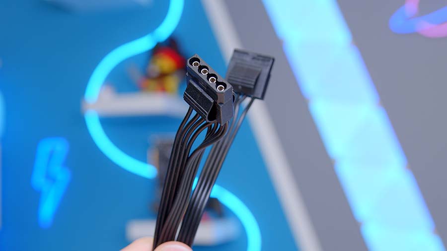
Molex Power
Molex power cables are included with almost every modern power supply despite being slowly deprecated and phased out for SATA. Traditionally, Molex has been used mainly for CD/DVD drives, IDE hard drives, and fans. While it isn’t likely that your PC build has a CD/DVD drive or an IDE hard drive, PSU manufacturers still support Molex power to accommodate these components.
Alternatively, some cheaper and older fans (commonly found in prebuilt machines) still use Molex power connectors, so those upgrading and re-wiring a prebuilt system might need to plug in a couple of Molex cables.
SATA Power
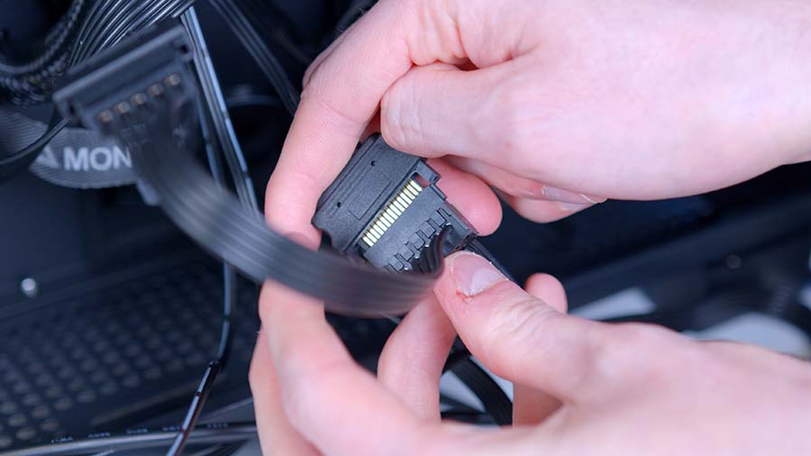
SATA power was introduced when the market moved to SATA-based storage devices, which are still commonly used today. SATA power cables are much easier to install than older solutions and are generally used for 3.5-inch and 2.5-inch drives. In the wake of NVMe storage (M.2 SSDs), it isn’t particularly likely that you’ll need to plug in SATA power.
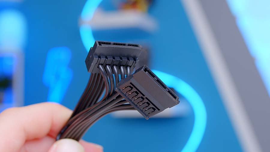
However, case and cooler manufacturers have adopted this power delivery standard for fans and RGB controllers. SATA power cables only plug in one way, and they have an angular notch that points downwards. These cables don’t click into place compared to other headers; they are friction fit, so we recommend being careful and using minimal force to get this cable plugged in.
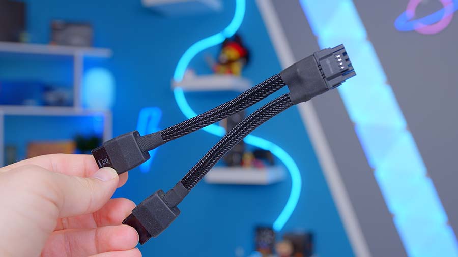
Power Supply Extension Cables
Power supply extensions are essentially universal extension cables that plug into the original cable and then into the chosen component. They can be handy for those with SFX power supplies that need a bit more length added to the end of the cable.
However, their primary purpose generally is to alter or unify the aesthetic of your cables. They come in a massive range of colours depending on the brand and are aimed at those who want to pick a specific colour theme. The EZDIY-FAB cables we used for this build guide are sleeved and have combs that help with cable management.
PC Case Front Panel Cables
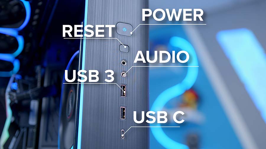
The next set of cables to be wired up is the front panel connectors. These cables allow you to use the IO at the front of your case, which includes the power and reset buttons, audio and microphone jacks, and USB ports.
HD Audio
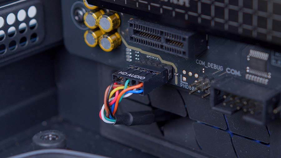
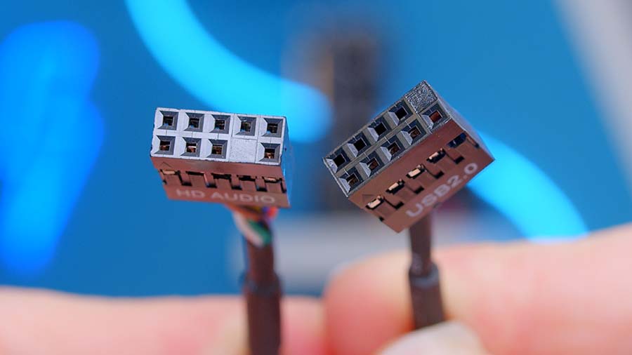
Starting with HD Audio, this is one of the most manageable cables to plug in, as the header can only go one way due to a blocked-out pin. The HD Audio pins are customarily located towards the bottom left of your motherboard, and we advise caution when plugging in the header, as the pins are somewhat delicate.
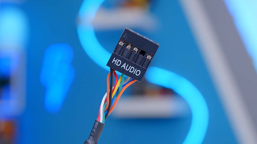
Plugging in this cable header will get the audio and microphone jacks working at the front of your case. There will be no click or indication that the header is plugged in, but we advise exercising caution not to mash up any pins.
It is also worth noting that HD Audio and USB 2.0 headers look very similar, but they can be identified by the blocked-out pins, which are in different spots on each header.
USB Headers
There are three types of USB headers that come with a PC build, these are: USB-C, USB 3.0, and USB 2.0, and this will depend on what front panel USBs your case and motherboard support.
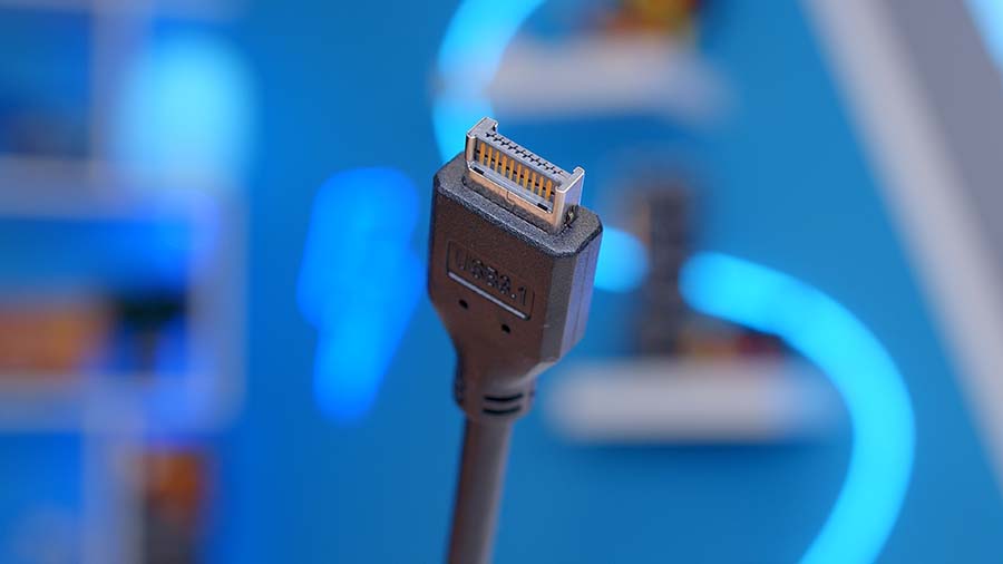
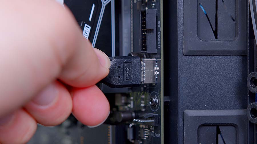
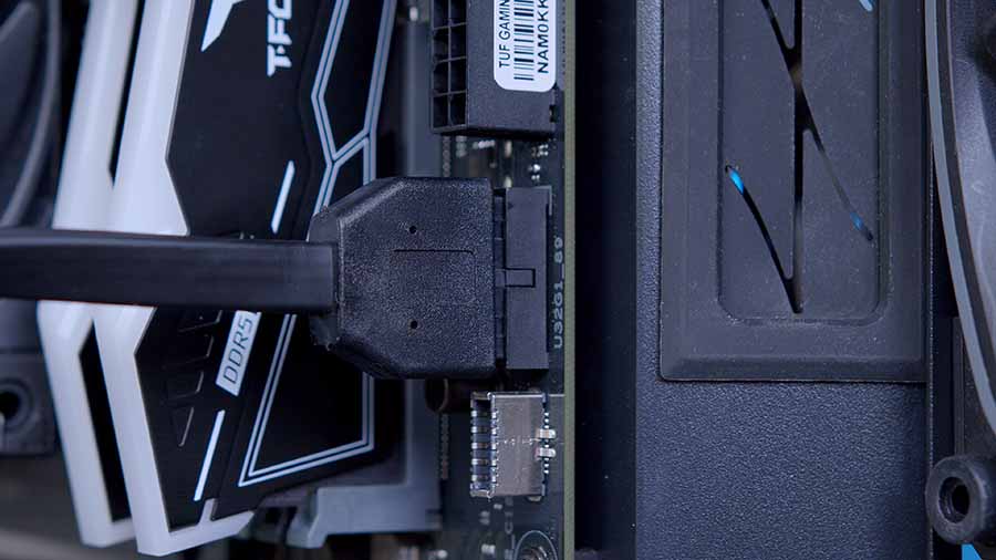
Modern motherboards and cases generally reserve the USB-C header for USB 3.2 Gen2x2 or USB 3.2 Gen2, rated at 20Gbps and 10Gbps, respectively. Plugging this in is pretty simple; the header is notched, so it can only go in one way. It is worth noting that the USB-C cable is quite fragile, so we advise only tensioning the cable a bit during cable management.
The USB 3.0 cable is commonly used to supply data and power for USB 3.2 Gen2 ports and previous USB 3.0 generations. Your case and motherboard manufacturer’s websites will note which standard the USB ports use, and we recommend checking these before purchasing to ensure all of the ports are utilising their full speeds.
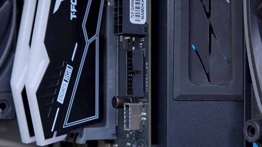
The USB 3.0 cable is notched very slightly along the middle of the header, and the port is commonly found above or below the USB-C header on the right-hand side of the motherboard.
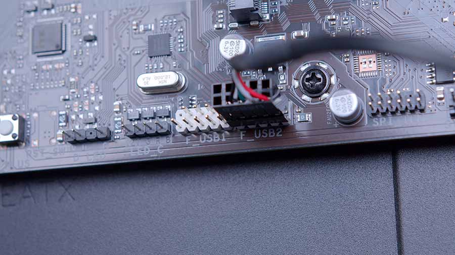
The final USB header to be plugged in is USB 2.0. The USB 2.0 header has become far less common across case front panels as most manufacturers have shifted to USB 3.0 and other high-speed options. However, USB 2.0 is still used in some capacity, primarily for CPU coolers, fan hubs, and RGB hubs. It provides a way for these components to give data readouts and be configured or customised through software such as Corsair iCUE, NZXT CAM, and others.
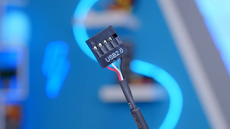
USB 2.0 headers are generally located at the bottom middle of a motherboard, but they can appear in other locations if you’ve picked up a pricier board with more front panel connections.
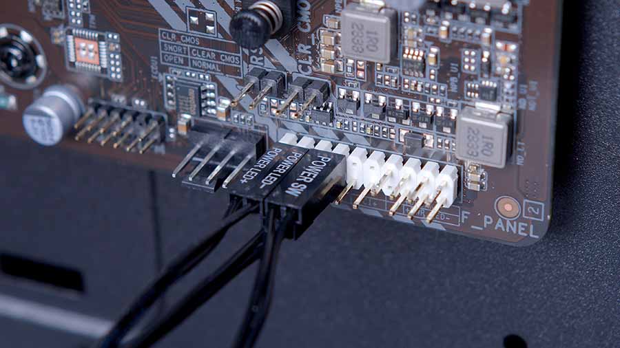
Power, Reset & HDD
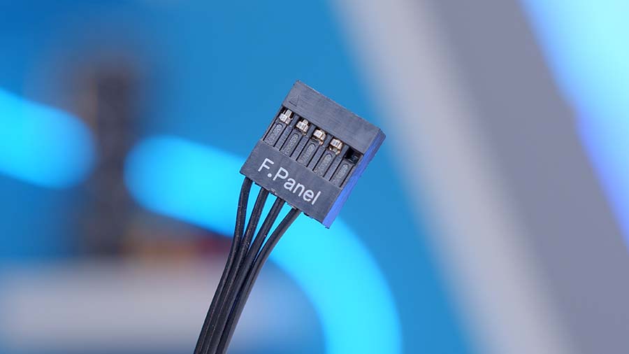
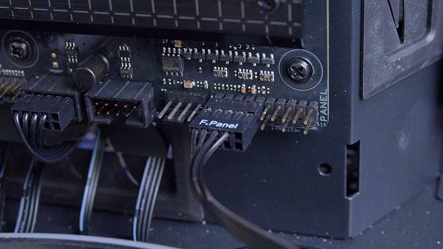
Commonly referred to as JFP1, this set of pins is responsible for switching on or resetting your PC and providing status LEDs for hard drives. There are two types of JFP1 headers that will differ depending on the case manufacturer. Our video guide used the Montech King 95 Pro case, which simplifies plugging in JFP1 by providing a full dedicated header. However, other manufacturers offer a different form of JFP1 where all pin-outs must be plugged in individually, which can be a hassle.
When plugging in JFP1, the main point is getting the positives and negatives the right way around. Now, there’s no need to worry about potential fires; if your power switch headers are reversed, your PC just won’t turn on. However, JFP1 is often a common point of failure if a PC build doesn’t switch on because it is very easy to muddle up the pins.
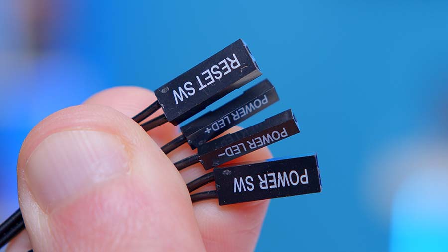
In our experience, if you have to plug in the individual JFP1 headers, the best way to ensure they’re all in the correct spot is if the header’s text is readable from the top. The words ‘POWER SW’ should be facing upwards, which means the positive is on the left, and the negative is on the right. This logic can also be applied to the other headers. Alternatively, JFP1 normally has a small diagram underneath it that highlights what each pin-out does.
The Power Switch and Reset headers are the most important ones that need to be plugged in, but we advise getting the Power LED, and HDD LED plugged in to ensure there’s no obvious point of failure if your PC doesn’t boot straight away.
RGB Headers
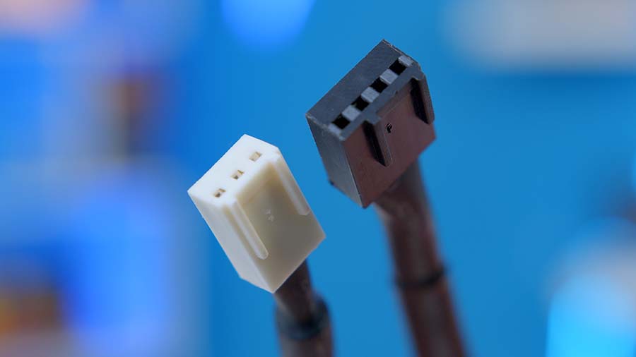
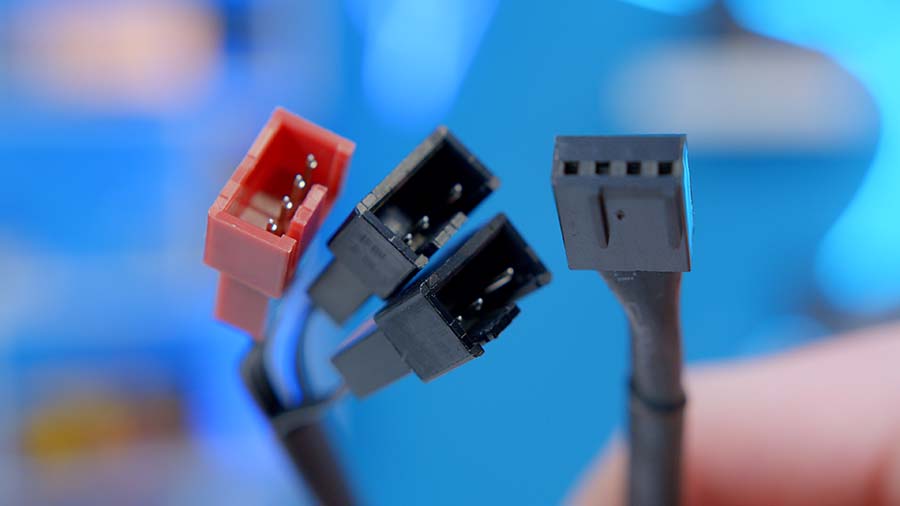
3-Pin & 4-Pin
This is where cabling can confuse the average PC builder, as there are standardised and non-standardised headers specific to major brands like Corsair and NZXT. Fortunately, 3-pin and 4-pin RGB are the universal headers that you’ll find across most modern motherboards.
Strangely, 4-pin is the older standard, while 3-pin is newer but the same size as 4-pin but with a pin-out missing in the middle. Without going on a tangent, 4-pin is a non-addressable form of RGB. So, if you’ve got any components that utilise the 4-pin standard, any lighting or colour effects assigned to these components will be the same across your entire PC build. What I mean by this is that if you prefer red for your RGB lighting, all 4-pin RGB nodes will be red.
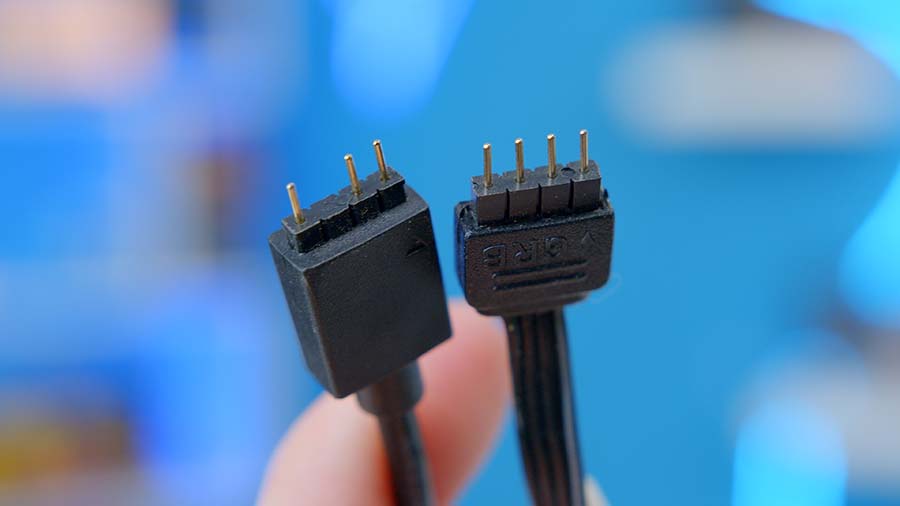
The 3-pin standard is effectively the same but adds addressability. So, instead of all the RGB lighting being the same, each RGB node can be configured individually, allowing you to customise lighting effects and colours freely.
Addressable RGB components are usually controlled by the software suite that matches your motherboard’s brand. For ASUS, this is Armoury Crate; for Gigabyte, the application is RGB Fusion; for MSI, this is Mystic Light; and for ASRock, this is RGB Sync. These applications are handy for synchronising lighting effects across your build components.
Corsair RGB
Unfortunately, the 3-pin and 4-pin standards are not the only viable ways to connect and set up RGB lighting. Brands like Corsair offer proprietary methods specific to their components that don’t work outside the Corsair ecosystem.
Corsair’s older standard is restricted to non-iCUE LINK components like the Corsair H150i Elite Capellix XT. Essentially, this standard is node-based, where all of the RGB components plugged in are assigned a node, and then lighting effects can be assigned to said node through the Corsair iCUE software.
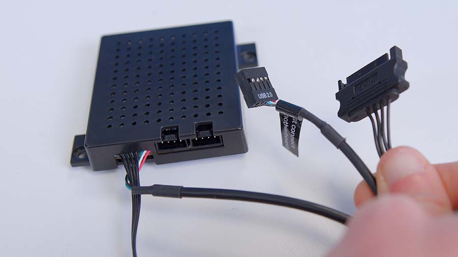
This older method of assigning RGB is centralised through Corsair accessories like the Commander Core XT, which plugs into your motherboard via a USB 2.0 header and is powered through SATA.
While the Corsair iCUE LINK standard is more refined, this older design is still comparatively better than standard 3-pin or 4-pin RGB, as the Corsair iCUE software makes configuration much more manageable. Furthermore, the iCUE RGB cables click into place, minimising the chance of any cabling getting loose.
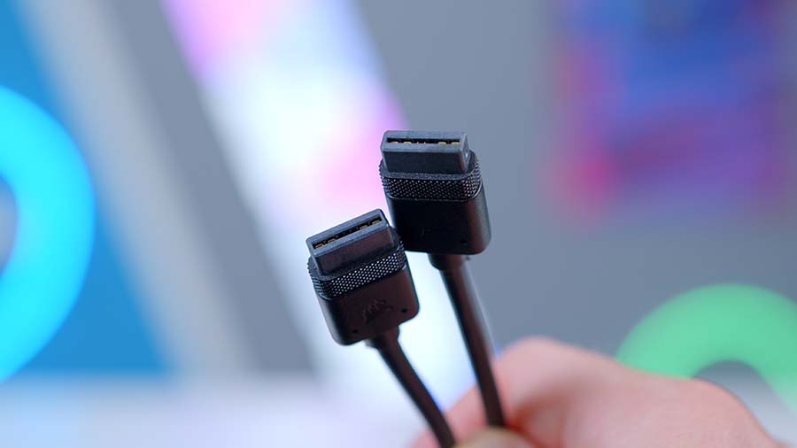
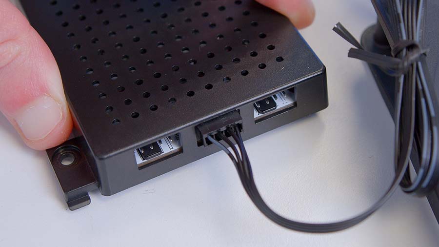
The most recent Corsair RGB system is known as iCUE LINK, which is much more refined than their older method. In layman’s terms, all iCUE LINK components are connected through a proprietary daisy chain mechanism. The iCUE LINK hub is the centre for power and data, offering two ports that support up to 14 devices, each using one cable.
Daisy chain systems are becoming more common as they simplify cabling and installation compared to traditional fans and coolers. The major caveat with proprietary RGB methods like iCUE LINK is price, but this is often worth it for those looking to avoid cable hassle.
NZXT RGB
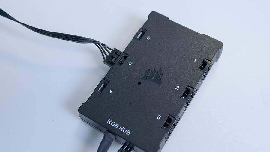
Another manufacturer worth highlighting that offers a proprietary RGB system is NZXT. While not as advanced as iCUE LINK, the NZXT Hub and CAM software is a solid competitor for those with NZXT-branded components.
Like Corsair, the NZXT RGB works off a centralised hub that plugs into your PC via USB 2.0 and SATA power. Any fans, CPU cooler headers, and RGB headers are then plugged into the hub, and then NZXT CAM needs to be installed and used to configure speeds and RGB. NZXT CAM has come a long way in recent years, and its UI is straightforward to use compared to other manufacturers.
Fans & Coolers
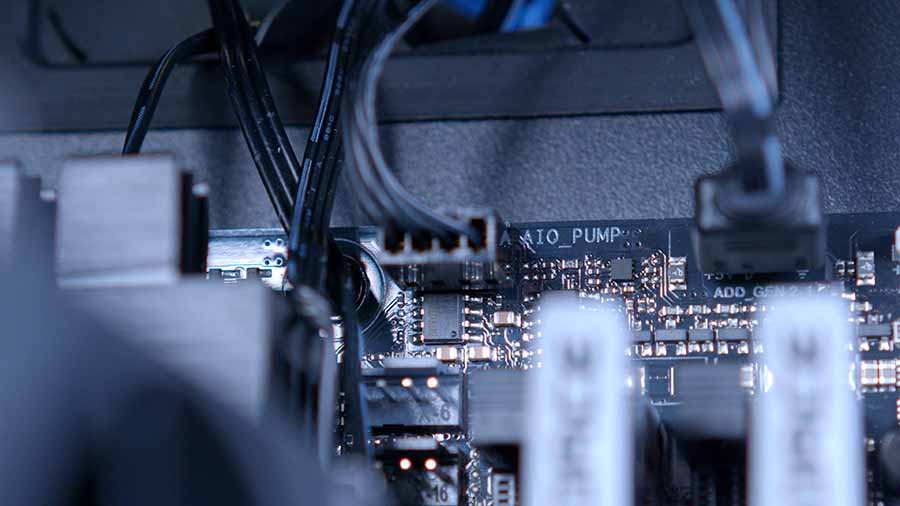
Two connectors are universal across fans and CPU coolers: 3-pin DC and 4-pin PWM. However, the header type your fans and CPU coolers use changes depending on the brand. Regardless of the header type, the most important thing to note is where these headers should be plugged in.
For those with a CPU air cooler, the cable should be plugged into the header marked ‘CPU_FAN’, while those with a liquid cooler should use the ‘AIO_PUMP’ header. These headers will power your air or liquid cooler but may also provide data if no additional USB 2.0 cables come with the component.
Cable Troubleshooting
Unfortunately, building a PC isn’t always sunshine and rainbows; troubleshooting is often a significant part of the process that can crop up during wiring. This is because it is easy to wire up a PC incorrectly. This isn’t to say that this is always the reason for a non-functioning PC build, but checking your cables is a good starting point because, often, this can be resolved relatively quickly.
One of the first steps we recommend is unplugging and plugging back in any power cables. Check both ends to make sure that the headers are secure, and give them a good tug, too, to ensure they don’t easily fall out. Those using extension cables should systematically check each extension to eliminate these as potential sources of the issue.
Moving onto front panel troubleshooting, we’ve found that this is one of the most common missteps when putting together a PC. Wiring up JFP1 can be both frustrating and finicky. If your PC isn’t powering on after checking the power cables, look at JFP1. The header might not be fully secured, or positive and negative might be the wrong way around. Regardless, take your time and ensure JFP1 is correctly wired.
If your fans aren’t spinning up, or the RGB lighting isn’t working, a few steps can be taken to get these working. Those using fan and RGB hubs will want to ensure the hub is powered correctly. This can involve unplugging the SATA header and then reseating it.
Alternatively, fan splitters can often be the culprit of fans not spinning up or being powered correctly. Splitters are helpful if there’s no included hub with the case or your motherboard doesn’t have enough fan headers. Some cheaper fan splitters may have a loose wire that causes power issues.
RGB connections can be a bit more complex to fix, especially if a fault crops up after cable management. However, there are a couple of quick steps that can solve issues. The first is reseating the RGB headers. Because there’s no firm way to secure the headers, they often come loose, so reseating after cable management is worth doing.
Any splitters could also have a loose RGB connection. We recommend using electrical tape to hold these together, which reduces the possibility of them coming loose again.
Final Thoughts
Wiring up a PC build is arguably one of the most arduous parts of the whole process. But it doesn’t have to be if you’re patient and take your time. If your PC build doesn’t power up immediately, fans aren’t spinning, or RGB isn’t working. Review these steps and systematically check each connection to ensure everything has been wired up correctly. It can also be a great idea to wire as you go during the middle of the build instead of leaving everything until the end.


